- 0502658911Toll Free Number
- [email protected]Email Address
- K.S.A - adammamOfice Location
| 1. | FUEL TANKS FOR DIESEL ENGINE : Fuel tanks are designed and compliance with NFPA20 standard. Fuel tanks are used from 50GPM to . 3000GPM capacity pumps | 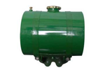 |
|---|---|---|
| 2. | PRESSURE RELIEF VALVE (PRY) : Tne Pressure Relief Valves is designed specifically to automatically relieve excess pressure in fire protection pumping systems_ Pilot controlled, it maintains constant system pressure at the pump discharge within very close limits as demands change | 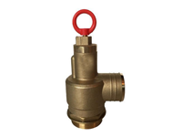 |
| 3. | CRY : Casing Relief Valve generally used for electric fire pump to release the extra pressure generated. Pressure can be adjusted according to the pump curve, Casing relief valves are FM approved and Ut. LISTED | 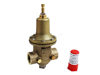 |
| 4. | FLOW METER SYSTEM : In place at, or, in addition to the hose valve header with hose valves, we offer a complete line of UL/FM approved flow meter which can adequately test the fire pump performance in Cases of liquid water supply, Available In calibrated venture design with a wall or pipe mounted dial meter reading in GPM. The system provides a +/- 1% accuracy. when installed properly. The venture principle provides a clog-free design and allows the most compact piping arrangement of any other flow meter design | 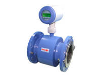 |
| 5. | Automatic Air Release Valve : The automatic air release valve releases air that may accumulate in the volute of the horizontal split case pumps. The valve is not required in self venting end suction pump, The minimum size is a ► inch inlet and the valve is installed at the top of the pump volute | 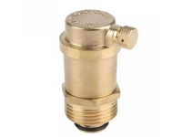 |
| 6. | Endesed Waste Cosa : The enclosed or open waste cone is connected directly to the main ref ref valve and provides a visual indication of the water discharging through the line. The fitting also increases the line size from the relief valve as required by NFPA 20_ The enclosed cone is provided with a sight glass | 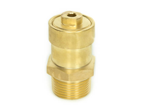 |
| 7. | Check Valve : A listed check valve is furnished to the piping arrangement as shown. They are extremely effective in preventing back pressure or back flow features a low 0.5 psi (0.038ox) cracking pressure differential and are capable of handling pressure to 275 psi (19 bar). | 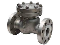 |
| 8. | Gauges : Suction and discharge gauge i s furnished for each f i re pump. With a minimum dial size of 3 1/2 Inch- the pressure range shall be twice the working pressure of the pump with a minimum of 200 psi, Ours tandard gauges read in psi, have a range of 300 psi and are compound pressure and vacuum type | 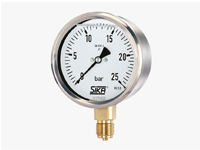 |
| 9. | Gate Valve : Listed gate or butter fly valves are to be used when required in the system or as shown in the above typical system, gutter fly valves are for use only in the discharge assembly. Valve opening I is same as the inside dia of pipe_ So that there i is I idle pressure drop through a gate valve. This valve i s used for throttling the f low. | 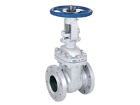 |